DSE 3110

Features:


Auto Start (Fire Pump) Controller

DSE3110 can be utilized as a Engine Control Unit   or Auto Start Module for single gen-set or engine only applications. The module has been designed to work with electronic and non-electronic engines, providing advanced engine monitoring and protection features.

Application :  Gensets , Engine driven pumps ( Fire Engine Pumps) , Compressors ect.

Brands:DSE

Description

DSE3110 is low cost Engine Control Unit or Auto Start Controller has basic facility to start / Stop in Manual as well as  Remote (Auto) mode. its compact design make it possible to use it small engines and solo operation applications.
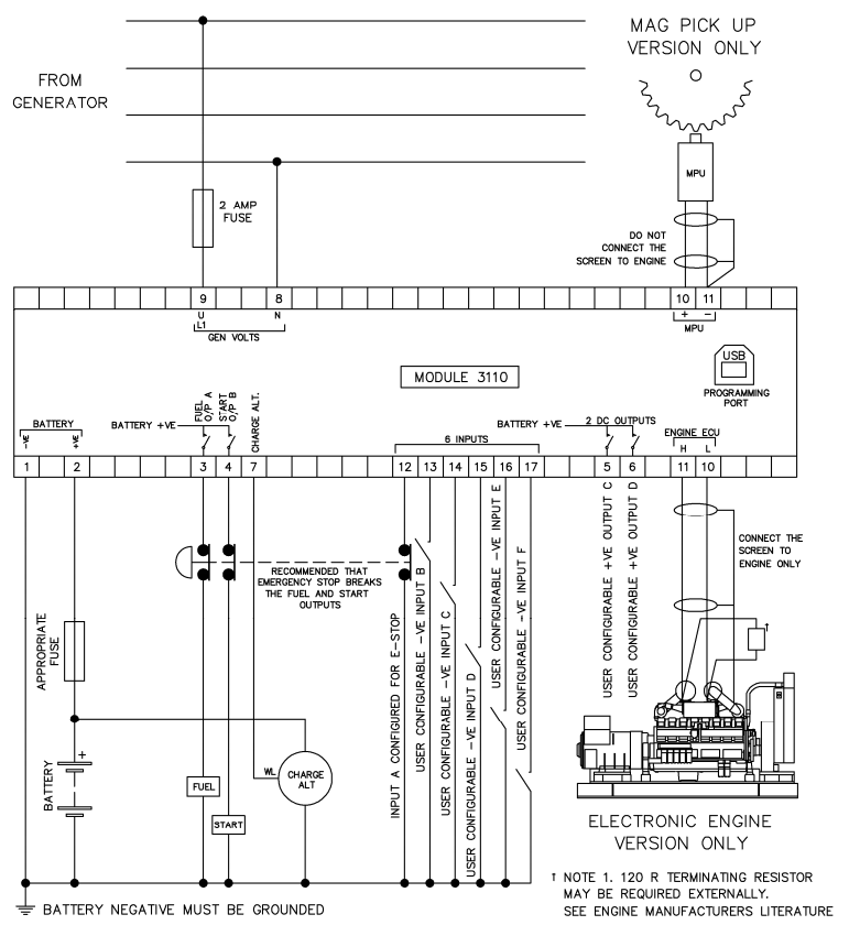
PRODCUT HILIGHTS

I/O
– Configurable inputs (6)
– Configurable DC outputs (2)
– Fuel and start outputs (configurable on CAN variant)
– Remote start input


COMMUNICATIONS
– USB for PC configuration


ENGINE COMPATIBILITY
– CAN engine support
– Conventional engine support (MPU & Hz)


CONFIGURATION
– DSE Configuration Suite PC software
– Front panel


KEY FEATURES
– Configurable timers and alarms
– Alternative configuration
– Tamper-proof hours counter
– Engine monitoring and protections
– Automatic shut-down
– Displays generator voltage, generator frequency, battery voltage and engine speed


Protection Functions

  • Under / Over Speed (with MPU only)
  • Low Oil Pressure (Switch input)
  • High Coolant (Water) Temperature (Switch input)
  • Low Fuel Level (Switch input)
  • Emergency Stop
  • Charger Alternator Fail
  • Low / High Battery Voltage

Variant

  • DSE 3110 – 02  (CAN) :  For use with electronic engines only.
  • DSE 3110 – 01  (MPU) : For use with non-electronic engines only (magnetic pick-up/alternator sensing).

Hardware

Dimension Details:

  • Over All Dimension – 98 mm x 79 mm x 40 mm
  • Panel Cut Out Dimension – 80 mm x 68 mm

DC SUPPLY

CONTINUOUS VOLTAGE RATING
8 V to 35 V Continuous

CRANKING DROPOUTS
Able to survive 0 V for 50 mS, providing supply was at least 10 V before dropout and supply recovers to 5 V. This is achieved without the need for internal batteries

CHARGE FAIL/ EXCITATION
8 V to 35 V fixed power source 2.5 W

NOMINAL STANDBY CURRENT
23 mA at 12 V, 18 mA at 24 V

MAXIMUM OPERATING CURRENT
35 mA at 12 V, 30 mA at 24 V

OUT PUTS
OUTPUT A (FUEL)
2 A DC at supply voltage
OUTPUT B (START)
2 A DC at supply voltage
AUXILIARY OUTPUTS C & D
2 A DC at supply voltage

GENERATOR 

VOLTAGE RANGE
15 V – 333 V AC (L-N)

FREQUENCY RANGE
3.5 Hz to 75 Hz

MAGNETIC PICK-UP 

VOLTAGE RANGE
+/- 0.5 V to 70 V

FREQUENCY RANGE
10,000 Hz (max)

Standards

Connection Diagram