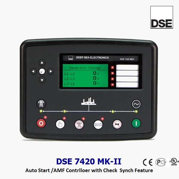
DSE 7420 MK-II

Features:


Auto Mains (Utility) Failure Control Module

DSE 7420 MK II enables the advance automation option for local  / cloud network facility for user. it is compatible over RS 485, RS 432, Ethernet over Modbus / TCP and compatible for Remote Monitoring Systems (RMS) / SCADA /  BMS ect. DSE Webnet  can make it possible to monitor & control DG Set remotely using software and app.

Application : Single & Multiple DG set AMF Operation / Dual Mutual Stand Operation

Categories: ,
Brands:DSE

Description

The DSE 7420 MKII is an intelligent, powerful auto mains (utility) failure control module with high-level features and functionality. The control module is the first module in the DSE range to include in-built SNMP and features an embedded web server. The module is suitable for a wide range of single-set gas and diesel applications.

PRODUCT HIGHLIGHTS

I/O
– Configurable digital inputs (8)
– Configurable analogue / digital inputs (6)
– Configurable outputs (8)
– Independent fuel & start outputs
– Configurable volt-free outputs (2)


COMMUNICATIONS
– SNMP, GET, SET & TRAP support
– MODBUS TCP IP / MODBUS RTU
– USB for PC configuration
– Simultaneous use of RS485, RS232 & Ethernet ports
– SCADA software
– DSE
WebNet® compatible


ENGINE COMPATIBILITY
– Conventional engine support (MPU & Hz)
– CAN engine support (Tier 4F / Stage 5)


CONFIGURATION
– DSE Configuration Suite PC software
– Configurable front panel (PIN protected)

ADVANCED FEATURES
– Embedded web server
– Mains (utility) supply monitoring
– Automatic transfer between mains (utility) & generator
– Supports 7 languages
– Crank disconnect on generator voltage
– Oil pressure disconnect delay
– Configurable icon screens
– CAN support for
DSEA108 AVR
– Charge alternator disable functionality
– Dedicated inputs for ECU specific operations
– Advanced PLC editor
– SMS alerts & control
– Dual mutual standby
– DSE
Net® expansion compatible


Protection Functions

  • Under / Over Speed (with CAN / MPU input only)
  • Low Oil Pressure
  • High Coolant (Water) Temperature
  • Low Fuel Level
  • Emergency Stop
  • Charger Alternator Fail
  • Low / High Battery Voltage
  • Mains Under / Over Voltage Protection (27/59)
  • Mains Under / Over Frequency Protection (81U/O)
  • Generator Under / Over Voltage Protection (27/59)
  • Generator Under / Over Frequency Protection (81U/O)
  • Generator Over Current Protection (50+51)
  • Generator Current Unbalance Protection (46)
  • Generator Earth Fault Protection (51N)
  • Generator Over Load Protection (KW)
  • Generator Reverse Power Protection (32)

Variant

  • DSE 7420 MK II – Advanced AMF Controller
  • DSE 2520 – Extended Display Module
  • DSE 2130 – Input Expansion Module
  • DSE 2157 – Output Expansion module
  • DSE 2548  – LED Expansion  module
  • DSE 890 – DSE Webnet Gateway (4G / Ethernet)

Hardware

  • Dimension Detail:

OVERALL SIZE :  245 mm x 184 mm x 51 mm
PANEL CUTOUT SIZE : 220 mm x 160 mm

  • DC SUPPLY

CONTINUOUS VOLTAGE RATING
8 V to 35 V Continuous
5 V for up to 1 Minute

CRANKING DROPOUTS
Able to survive 0 V for 100 mS, providing supply was at least 10 V before dropout and supply recovers to 5 V. This is achieved without the need for internal batteries

MAXIMUM OPERATING CURRENT

510 mA at 12 V, 240 mA at 24 V

MAXIMUM STANDBY CURRENT
330 mA at 12 V, 160 mA at 24 V

CHARGE FAIL/EXCITATION RANGE

0 V to 35 V

  • INPUTS

DIGITAL INPUTS A-H
Negative Switching

ANALOGUE INPUTS A,B, E & F
Configurable as
Negative Switching Digital Input
0 V to 10 V Sensor
4mA to 20mA Sensor
Resistive Sensor

ANALOGUE INPUTS C & D
Negative Switching Digital Input
Resistive Sensor

  • OUTPUTS

OUTPUT A (FUEL)
15 A DC at supply voltage

OUTPUT B (START)

15 A DC at supply voltage

OUTPUTS C & D

8 A AC at 250 V AC (Volt free)

AUXILIARY OUTPUTS E,F,G,H,I & J

2 A DC at supply voltage

  • GENERATOR & MAINS

VOLTAGE RANGE
15 V to 415 V AC (Ph-N)
26 V to 719 V AC (Ph to Ph)

FREQUENCY RANGE
3.5 Hz to 75 Hz

  • MAGNETIC PICK UP

VOLTAGE RANGE
+/- 0.5 V to 70 V

FREQUENCY RANGE

10,000 Hz (max)

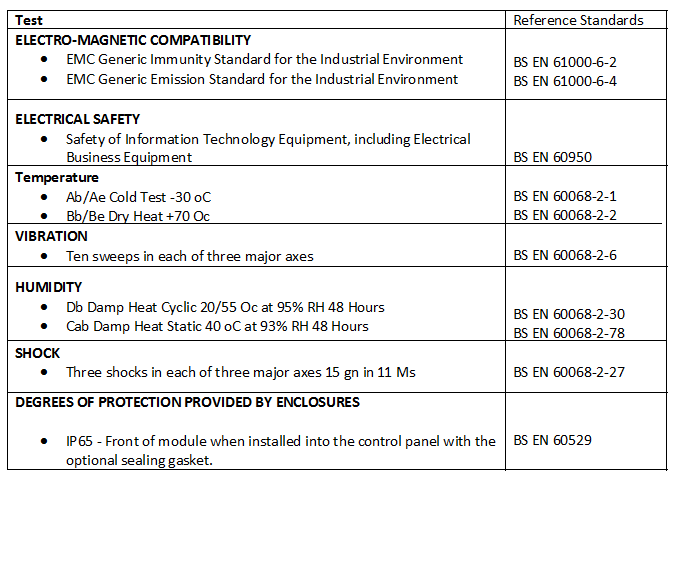
Standards

Connection Diagram